Sensory-Motor Control, ROS2 + TB4 Recap, and RViz
Today's Class Meeting
- Learning about sensory-motor control and PID control - here's a link to today's slides
- Reviewing ROS2 concepts and the fundamentals of controlling a Turtlebot4
- Introduction to RViz
Sensory-Motor Control and PID Control
The content in this section summarizes the main points covered in today's lecture.
One foundational concept in robotics is sensory-motor loops and control. The robot's sensor readings inform how it moves in its environment, which will then influence the next sensor readings from the robot, and the loop goes on. One of the most well known sensory-motor control methods is PID (Proportional Integral Derivative) control, which is depicted in the block diagram below:

The PID control function can be represented as follows:
\( u_t = K_P \cdot e(t) + K_I \cdot \int_0^1 e(\tau)d\tau + K_D \cdot \frac{d}{dt} e(t) \)
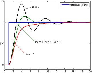
Where KP, KI, and KD, are the constant coefficients for the proportional, integral, and derivative terms; e(t) represents the difference between the goal (setpoint) and the sensor measurement (process variable). The three following graphs display how a system responds to a step change in the setpoint to each component of the PID controller separately and all the components combined at different values of KP, KI, and KD.

Response of the process variable to a step change of the setpoint for different values of KP. Source: Wikipedia.
Response of the process variable to a step change of the setpoint for different values of KI. Source: Wikipedia.
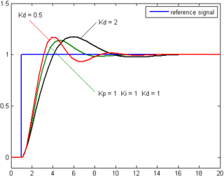
Response of the process variable to a step change of the setpoint for different values of KD. Source: Wikipedia.
This YouTube video by Brian Douglas is a great resource providing a clear explanation of the PID controller.
Looking Ahead
In our next lab, you'll have the opportunity to implement proportional control on the turtlebots by programming them to follow a line on the floor.
RViz
RViz is a powerful tool that enables you to visualize the robot's sensor data and other information in real-time. In the gif below, you can see RViz displaying the camera feed and LiDAR data I captured from one of the Turtlebot4 robots.
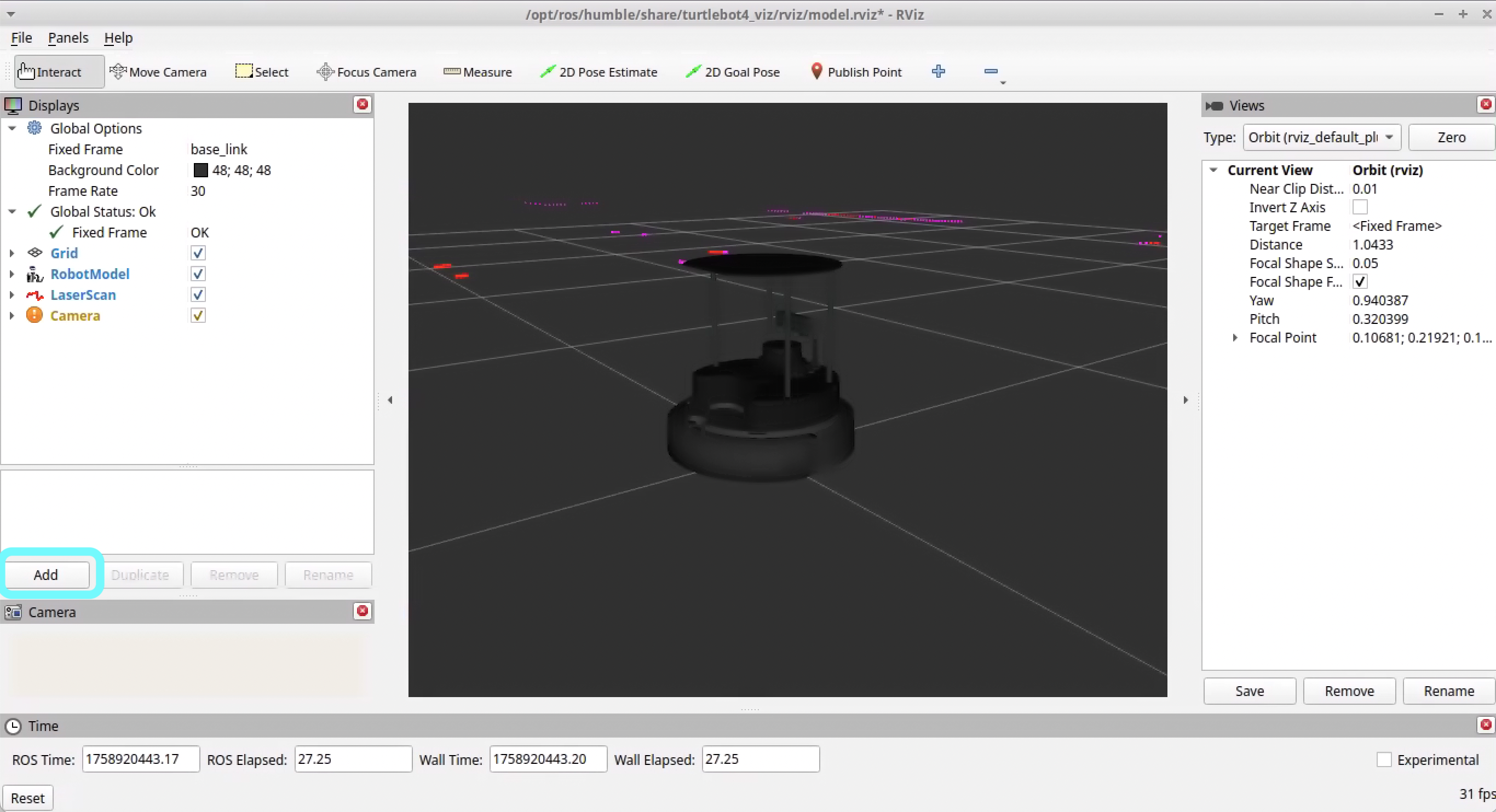
In order to use RViz with your Turtlebot4, first ensure that your ROS2 environment is set up to connect with the Turtlebot4 you are using (for this example let's say I'm using TB 03). Then, in a terminal, run:
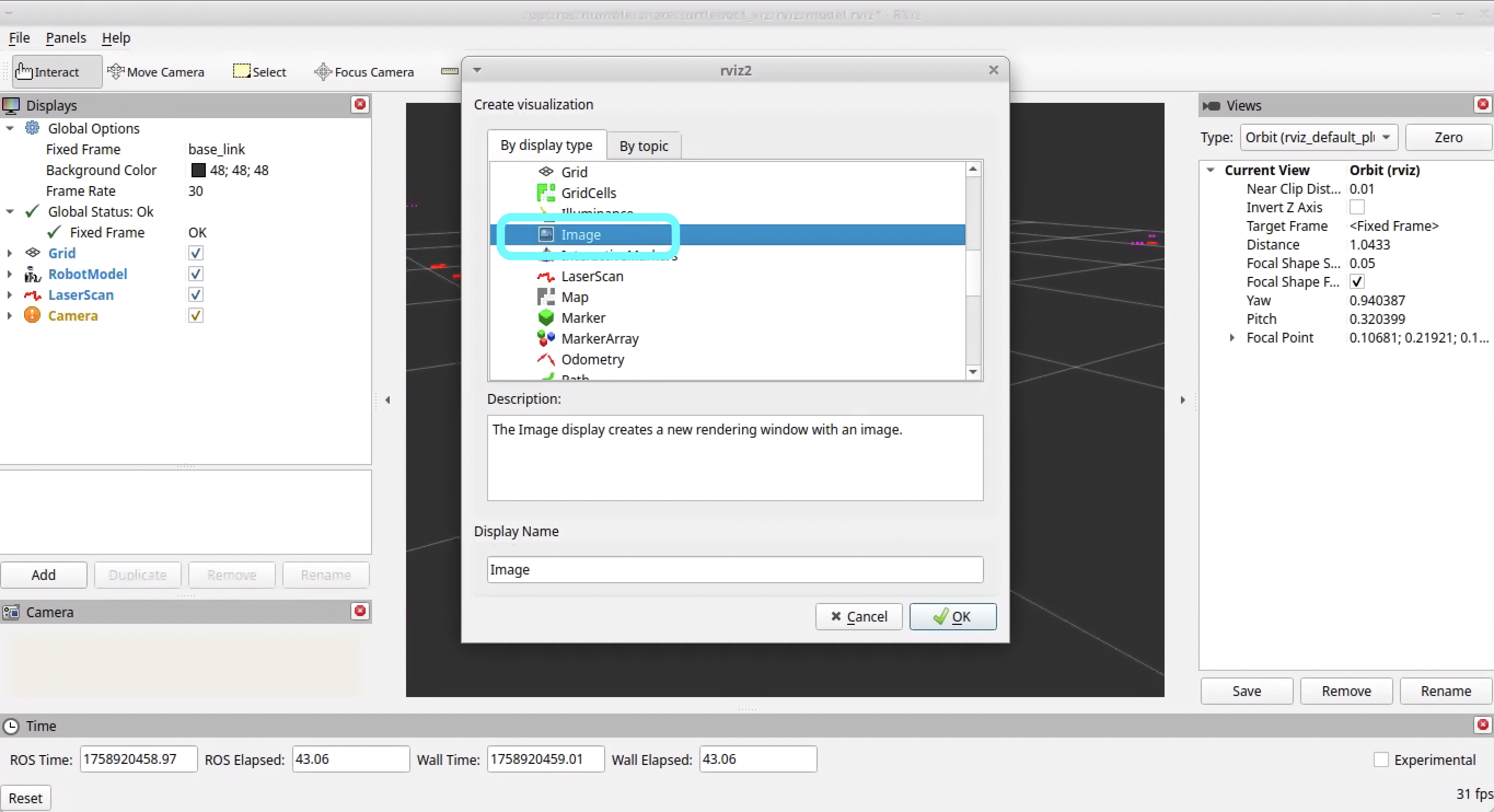
$ ros2 launch turtlebot4_viz view_model.launch.py namespace:=/tb03Note that the namespace should match the name of the Turtlebot4 you are using. You should see a window pop up that looks something like the image below. The LiDAR information should already be showing. To add the camera feed, click the "Add" button in the bottom left corner of the RViz window.
Then, select "Image" from the list and click "OK".
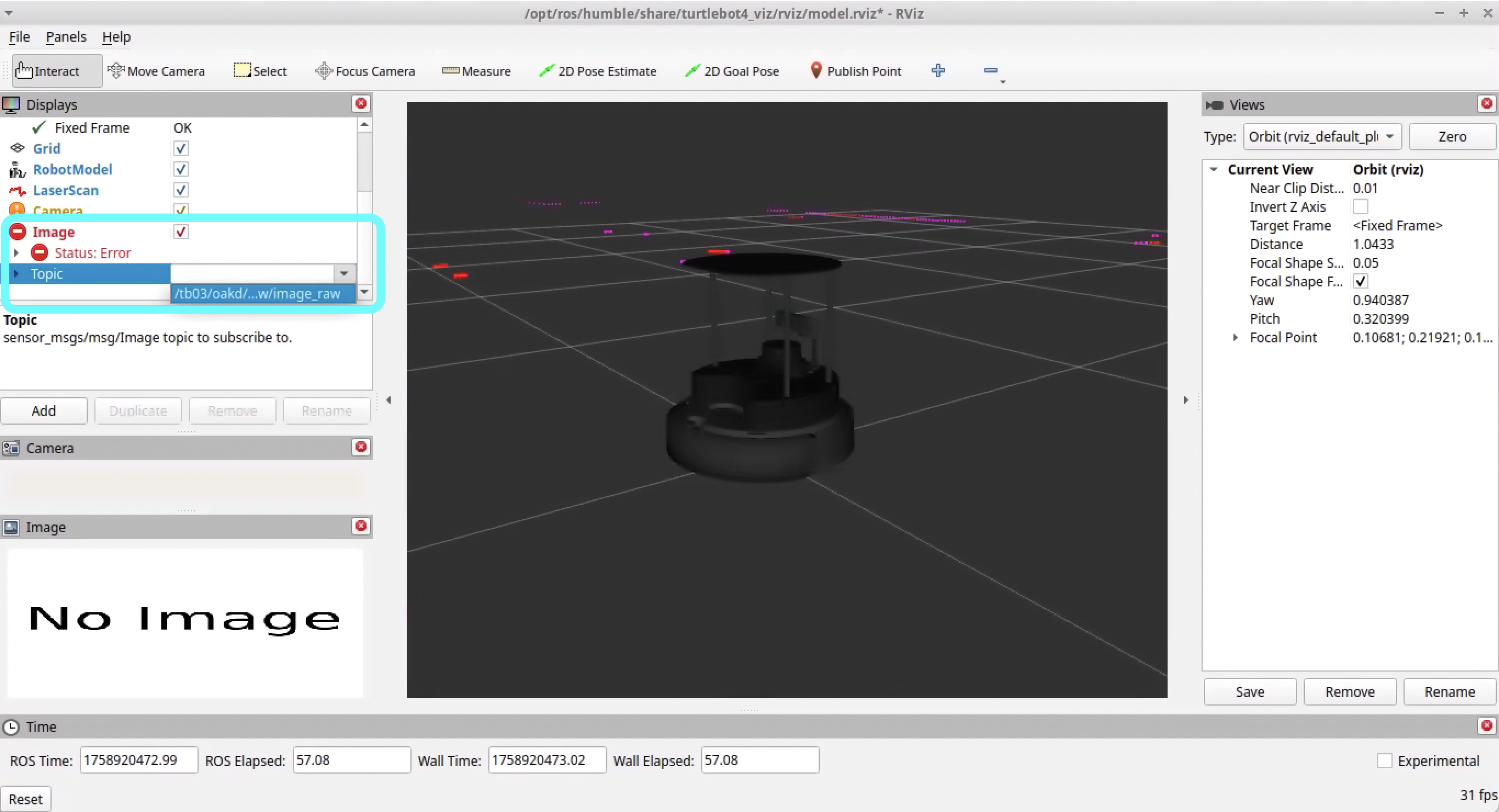
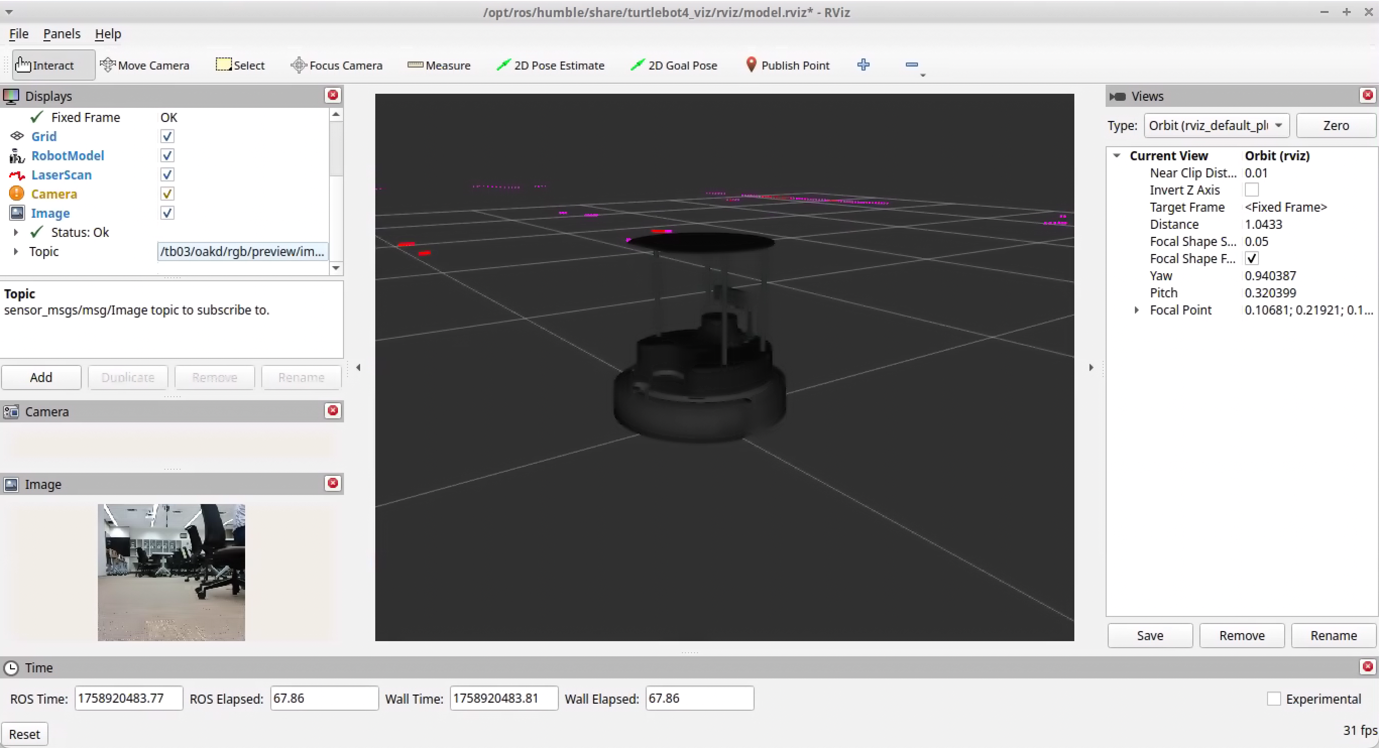
Now, you'll just need to set the topic to the camera feed topic for your Turtlebot4. For TB 03, the camera feed topic is /tb03/oakd/rgb/preview/image_raw.
You should now see the camera feed in RViz!
Class Meeting 2 Homework
For your Class Meeting 2 Homework, submit the following via Canvas/Gradescope by 2:00pm on Friday, October 3rd:
- Screenshot of RViz displaying the camera feed and LiDAR data