CMSC15100 Autumn 2010: Project 2
Due Wednesday, November 24 at 10pm.
Setup
This assignment should be done using the
Advanced student language.
Overview
In this project, you will extend your simple raytracer from
Project 1
with additional object and light types, and a more general shading model.
Make sure that your submitted solution compiles; i.e., that there are no syntax errors
or undefined variables.
Submissions that do not compile will get 0 points!!!
Step 1
Your first step should be to address any issues raised by the grader for your Project 1.
Program organization
Your program should be clearly organized into sections with your data definitions at the
top of your code.
Extending the ray tracer
Data definitions
For this project, you will have to both modify and add to your data definitions.
Read the descriptions carefully.
Surfaces
A surface defines the properties of an object's surface and is defined
by
- Cd --- the diffuse color (rgb)
- Cs --- the specular color (rgb)
- n --- the Phong exponent (num)
Objects
For this project, you will render only two kinds of object: spheres
and planes.
A sphere has a position (vec3),
a radius (num),
and a surface color (surface).
Note that the surface is now specified as a surface value.
A plane has a normal (vec3), a signed distance
from the plane to the origin in the direction of the normal (num),
and a surface (surface).
The normal vector determines which side of the plane is the front.
For example, the plane with surface s
that is defined by Z = 5, can be defined as either facing the origin
(make-plane (make-vec3 0 0 -1) 5 s)
or facing away from the origin
(make-plane (make-vec3 0 0 1) -5 s)
Notice that if the plane is facing the origin, then the distance will be positive, while if
it is facing away from the origin, the distance will be negative.
Lights
A light is either a dir-light
or a point-light
A dir-light is represented by a direction vector
that points toward the light source (a unit vec3)
and a color (rgb).
A point-light is represented by a position
(vec3)
and a color (rgb).
You may find the following helper functions useful in your code (you may have to adjust the
field names to match your data definitions):
(define (light-direction pos light)
(cond
[(dir-light? light) (dir-light-dir light)]
[(point-light? light)
(v3-normalize (v3-sub (point-light-pos light) pos))]
[else (error 'light-direction "not a light")]))
(define (light-rgb light)
(cond
[(dir-light? light) (dir-light-rgb light)]
[(point-light? light) (point-light-rgb light)]
[else (error 'light-rgb "not a light")]))
Scenes
A scene has a background color (rgb),
a list of objects (list object),
a list of lights light source (list light), and
an ambient light level (rgb).
Note that both the background color and ambient light colors are now specified as RGB values.
Cameras
Cameras are as in Project 1.
Hit tests
A hit-test is either a hit or 'miss, where
a hit consists of the distance along the ray where the hit occurs,
the surface color at the hit point (surface), and
the surface normal at the surface location (a unit vec3).
Intersection testing
You will need to add a new intersection test for planes and you may need to modify your sphere-intersection
test for changes in your data definitions.
Plane intersection testing
Given a ray R(t) = Ro + tRd and a plane defined by its normal Pn and distance to the origin d,
the point of intersection is given by the formula:
t = -(Pn dot Ro + d) / (Pn dot Rd)
If abs(Pn dot Rd) < ε (for small ε) then the ray is esentially parallel to the
plane and we will treat it as a miss.
Illumination model
For this project, your ray tracer will model both diffuse light and reflected light.
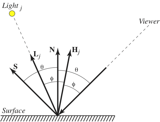
The following picture shows the situation where a ray R(t) = Ro + tRd
has hit a surface:
The lllumination at that point is computed as follows:
where
- Ia is the ambient light in the scene,
- Cd and Cs are the surface diffuse and specular colors,
- N is the unit normal at the point of intersection,
- Lj is the unit direction vector of the jth light,
- Ij is the color of the jth light,
- Hj is the unit vector in the direction halfway between the viewer and Lj,
- n is the Phong exponent of the surface,
- S is the unit reflection vector, and
- Is is the illumination from direction S
We will break the computation of this function into three parts
-
The ambient color, which is computed by modulating the scene's ambient light
with the surface's diffuse color
-
The illumination from the lights in the scene. You should write a function
illuminate (described below) that computes both
the diffuse and specular contributions for a single light.
We can then compute the light from all of the lights in the scene by adding
the contributions from each light (think foldl).
-
The light reflected off the surface.
To compute this value, we will recursively trace the reflection ray S
and modulate the resulting color with the surface's specular color.
To get the final light at the surface, we sum these three components.
The lighting function (described below) is responsible
for summing the illumination from the lights, as well as adding in the ambient and
reflected light.
The most complicated part of the illumination model is dealing with the lights.
You should write a function that computes the illumination (both diffuse and specular) for a single
light
(define (illuminate objs R hit) ...)
This function should first test to see if the light is behind the surface (i.e., the
(N dot Lj) <= 0) or the intersection point is in shadow.
In that case, you can return black without any further computation.
Note that if (N dot Lj) > 0), then you do not need the
max calls that are in the illumination equation.
This function should use the shadowed-by? to detect shadows
(if you wish, you may merge the shadowed-by?
code into illuminate).
The Hj vector is computed by
(define Hj (v3-normalize (v3-sub Lj Rd)))
To compute the illumination Is from direction S, we recursively trace
the ray that starts at the intersection position and has direction S.
As with shadow rays, you will want to start a small distance off the surface to avoid
precision problems.
The vector S is called the reflection vector and forms the same angle with
N as the vector to the viewer does (this angle is labeled θ in the picture).
It can be computed by
(define S (v3-add (v3-scale (* -2 (v3-dot Rd N)) N) Rd))
(The proof that this is a unit vector is left up to the reader).
Ray tracing
Because the tracing of rays and computation of lighting is mutually recursive, you will need
a different structure for this part of the code.
We suggest defining the trace function as before,
with the revised type
(define (trace scene) ...)
Inside the trace function, you should define two mutually recursive
functions: one that computes the lighting (as described above) and one that traces a ray through
the scene.
The types of these functions should be
To keep the computation bounded, we limit the depth of recursive calls by adding an
extra argument to both functions that is decremented when lighting
calls tr.
When the value gets to zero, then tr should just return
black instead of testing for intersections.
Finally, the raytrace function will have to be modified
to take a depth limit.
(define (raytrace cam scene depth) ...)
Examples
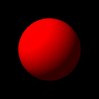
Here are new versions of the Project 1 test cases. They should render as before.
(define (diffuse-surf c) (make-surface (name->rgb c) (name->rgb 'black) 0))
(define test-sphere-1 (make-sphere (make-vec3 0 0 3) 1 (diffuse-surf 'red)))
(define test-camera-1
(make-camera -5 200 200))
(define test-camera-2
(make-camera -2.5 400 200))
(define test-scene-1
(make-scene
(make-rgb 0 0 0)
(list test-sphere-1)
(list (make-dir-light (v3-normalize (make-vec3 -1 1 -1)) (name->rgb 'white)))
(make-rgb 0.2 0.2 0.2)))
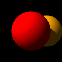
(define test-sphere-2 (make-sphere (make-vec3 1 0 5) 1 (diffuse-surf 'orange)))
(define test-scene-2
(make-scene
(make-rgb 0 0 0)
(list test-sphere-1 test-sphere-2)
(list (make-dir-light (v3-normalize (make-vec3 -1 1 -1)) (name->rgb 'white)))
(make-rgb 0.2 0.2 0.2)))
(define test-sphere-3 (make-sphere (make-vec3 1 -1 4) 2 (diffuse-surf 'orange)))
(define test-sphere-4 (make-sphere (make-vec3 -1 1 2.75) 0.6 (diffuse-surf 'blue)))
(define test-scene-3
(make-scene
(make-rgb 0 0 0)
(list test-sphere-3 test-sphere-4)
(list (make-dir-light (v3-normalize (make-vec3 -1 1 -0.5)) (name->rgb 'white)))
(make-rgb 0.2 0.2 0.3)))
Note that you should be able to increase the depth value to 2 or 3 without changing the
result on these tests.
Here are the resulting images for the scenes:
(raytrace test-camera-1 test-scene-1 1)
(raytrace test-camera-1 test-scene-2 1)
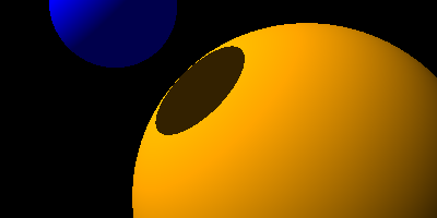
(raytrace test-camera-1 test-scene-3 1)
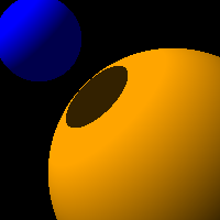
(raytrace test-camera-2 test-scene-3 1)
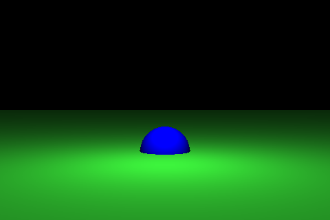
Here is an example that uses a diffuse plane and a point light.
(define test-camera-3
(make-camera -2 480 320))
(define test-plane-1
(make-plane (make-vec3 0 1 0) 1 (make-surface (make-rgb 0.2 0.8 0.2) (make-rgb 0 0 0) 1)))
(define test-sphere-5 (make-sphere (make-vec3 0 -1 6) 0.6 (diffuse-surf 'blue)))
(define test-scene-4
(make-scene
(make-rgb 0 0 0)
(list test-plane-1 test-sphere-5)
(list (make-point-light (make-vec3 0 1 4) (name->rgb 'white)))
(make-rgb 0.2 0.2 0.2)))
(raytrace test-camera-3 test-scene-4 2)
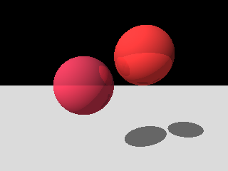
Here is an example that tests reflections.
(define test-camera-4
(make-camera -1 320 240))
(define test-scene-5
(make-scene
(make-rgb 0 0 0)
(list
(make-plane (make-vec3 0 1 0) 3 (diffuse-surf 'white))
(make-sphere (make-vec3 -1 0 3) 1
(make-surface (make-rgb 0.7 0.2 0.3) (make-rgb 0.2 0.04 0.06) 1))
(make-sphere (make-vec3 1 1 3) 1
(make-surface (make-rgb 0.8 0.2 0.2) (make-rgb 0.2 0.04 0.04) 1)))
(list (make-dir-light (v3-normalize (make-vec3 -1 1 -1)) (make-rgb 0.8 0.8 0.8)))
(make-rgb 0.4 0.4 0.4)))
(raytrace test-camera-4 test-scene-5 3)
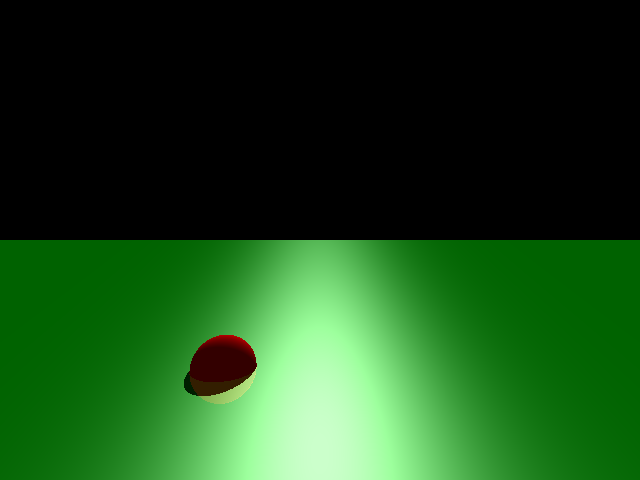
And here is an example that tests specular highlights.
(define test-scene-6
(make-scene
(make-rgb 0 0 0)
(list
(make-plane (make-vec3 0 1 0) 2 (make-surface (make-rgb 0 0.6 0) (make-rgb 1 1 1) 20))
(make-sphere (make-vec3 -1.5 -2 4) 0.5 (diffuse-surf 'red)))
(list
(make-dir-light (v3-normalize (make-vec3 0 2 3)) (make-rgb 0.8 0.8 0.8)))
(make-rgb 0.2 0.2 0.2)))
(raytrace test-camera-4 test-scene-6 2)

Here is a version at twice the resolution
(raytrace (make-camera -1 640 480) test-scene-6 2)
Last revised: November 23, 2010.