This assignment should be done using the Advanced student language.
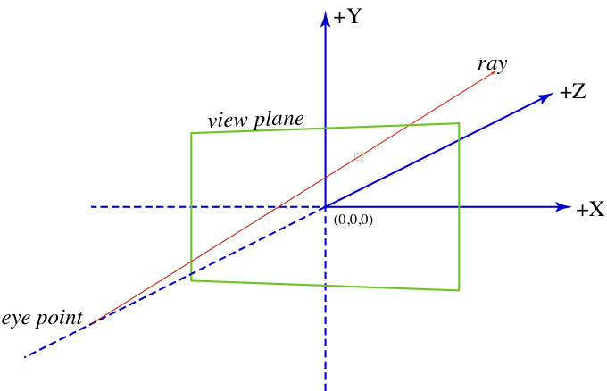
In this project you will implement a simple raytracer. The basic idea of raytracing is that you trace a ray from the camera (or eye) position through the center of each pixel and into the scene.
By testing the ray against the objects in the scene, you can determine which object contributes color to the pixel (note that the ray may intersect multiple objects, so you must determine the closest one). Once the object intersection has been determined, you must test to see if the point is in shadow. With that information, you can compute the lighting information and, thus, the color of the pixel.
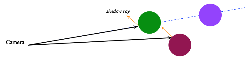
In the following figure, we see two rays. The first intersects both the green and purple spheres, but, because the green sphere is closer, we will render a green pixel for the ray. The other ray hits the maroon sphere, but the hit point lies in the shadow of the green sphere.
In this section, we provide an overview of how you should structure your code. There are many parts to this project and, while most of them are straightforward, the project as a whole is larger than the previous assignments. Thus, you should start early and make sure to test each component independently.
You may want to consult the discussion below of the support code before reading this section.
You will need a number of data definitions for your program. These should be placed at the beginning of your code.
For this project, you will render only one kind of object: spheres. A sphere has a position (vec3), a radius, and a surface color (rgb). Note that the surface color is represented as an RGB triple and not a Racket color value.
A light is represented by a direction vector pointing toward the light (a unit vec3) and a color (rgb).
A scene has a background color (color), a list of objects, a directional light source (light), and an ambient light level (rgb). Note that we use a Racket color value to specify the background color, but an RGB value for the ambient light.
A camera is specified by a Z-axis coordinate and the width and height of the image.
A hit-test is either a hit or 'miss, where a hit consists of the distance along the ray where the hit occurs, the surface color at the hit point (rgb), and the surface normal at the surface location (a unit vec3).
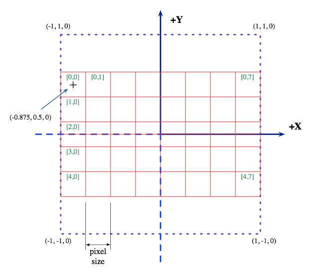
For each pixel in the image, you will have to compute a ray that starts at the camera position and passes through the center of the pixel. For example, the following figure shows the layout of an 8x5 image. Because the image is wider than it is tall, the width determines the pixel size, which is (2 / 8 = 0.25). The center of the upper-left pixel (pixel [0,0]) is (-0.875, 0.5, 0).
The heart of a ray tracer is the function that tests for intersections between rays and objects. You should write a general function for testing for intersection.
;; intersect : ray object -> hit-test ;; test an object obj against the ray R for intersection. If they intersect, return the ;; hit information; otherwise return 'miss (define (intersect R obj) ...)
This function should test the type of the object (e.g., sphere?) and call an object-specific intersection test.
There are two approaches to testing the intersection of a ray and a sphere: the algebraic method and the geometric method. You can find a description of these two approaches here.
Once you have determined that a ray intersects a sphere, you need to build a hit object. This object includes the value of t for the intersection point, the color of the object, and the surface normal at the intersection point. A surface normal is a unit vector that is perpendicular to the surface. For a sphere S that is intersected by the ray R at R(t), the normal vector can be computed as
(v3-normalize (v3-sub (ray-position R t) (sphere-center S)))
Once the closest hit has been determined, you will need to test to see if the hit location is in shadow. To be in shadow means that there is an object between the hit location and the light source. You can test this property by tracing a ray (called a shadow ray) from the hit location in the direction of the light. If it does not intersect with any objects, then the hit location is not in shadow. Write the following predicate to test this property:
;; shadowed-by? : vec3 -> light -> object -> boolean ;; test to see if a position pos receives illumination from the ;; light or is shadowed by the object. (define (shadowed-by? pos) ...)
There is one subtlety to this function, which is that you have to be careful to avoid self shadowing. The easiest way to do this is to start the shadow ray slightly off the surface. For example, if p is the hit location and d is the unit vector pointing toward the light, then create the initial ray as
(make-ray (v3-add p (v3-scale 0.0001 d)) d)
Using the shadowed-by? predicate, you can implement a function that computes the lighting for a hit-test.
;; lighting : scene -> ray hit-test -> color ;; given a scene, a ray and a hit-test for the ray, compute the color for this hit-test. ;; If it is 'miss, then the color is the scene's background color, otherwise it is ;; determined by the diffuse lighting at the hit point (define (lighting scene) ...)
If the hit location is in shadow, then the color is determined by modulating the surface color by the scene's ambient light (using rgb-modulate). If the hit location is not in shadow, then we modulate the surface color with the sum of the ambient light and the diffuse lighting of the surface.
The diffuse lighting of a surface is computed by multiplying the dot product of the surface normal and the light vector (both unit vectors) by the light's RGB value. If the dot product is negative, the light is behind the surface and we treat it as shadow. The following Racket code implements the diffuse-lighting computation:
(rgb-scale (max 0 (v3-dot normal l-dir)) l-color)
where normal is the surface normal, l-dir is the light-direction vector, and l-color is the light's color.
Once the RGB value for the hit has been computed, it must be converted to a Racket color value using the provided rgb->color function.
The final part of the project is the computation of the image by tracing the rays. You should break this part into two functions. The first is a higher-order function that traces single ray against the scene. It must test the for intersections with the scene's objects and find the closest hit (or 'miss). Then it can use the lighting function to compute the color.
;; trace : scene -> ray -> color ;; Given a scene, return a function for tracing the ray through the scene to compute a color (define (trace scene) ...)
Finally, we can combine the above functions with the build-image function to implement the raytracer.
;; raytrace : camera scene -> image ;; generate an image for the given camera and scene (define (raytrace cam scene) ...)
There are two files that you will need to download for this project.
This file provides an operation to generate an image from a fucntion that computes individual pixels. This function will serve as the top-level loop for your ray tracer.
;; build-image : nat nat (nat nat -> color) -> image ;; creates a width x height sized image where the (i,j)'th pixel is ;; computed by the expression (f i j) (define (build-image width height f) ...)
This file contains some additional definitions, which are described below. You should put your name at the top of the file and add your code at the bottom. Note that you may not need all of these operations.
;; a vec3 represents a 3D vector or position (define-struct vec3 (x y z)) ;; v3-add : vec3 vec3 -> vec3 ;; add two vectors (define (v3-add u v) ...) ;; v3-sub : vec3 vec3 -> vec3 ;; subtract two vectors (define (v3-sub u v) ...) ;; v3-scale : num vec3 -> vec3 ;; multiply a vector by a scalar (define (v3-scale s v) ...) ;; v3-dot : vec3 vec3 -> num ;; dot product (define (v3-dot u v) ...) ;; v3-length : vec3 -> num ;; return the length of a vector (define (v3-length v) ...) ;; v3-normalize : vec3 -> vec3 ;; scale a vector so that it is a unit vector; returns the zero vector on very short inputs (define (v3-normalize v)
;; a ray is defined by its origin (a position) and a direction (a unit vector). We can view ;; a ray as a function from scalars to positions: ;; ;; R(t) = origin + t*dir ;; (define-struct ray (origin dir)) ;; ray-position : ray num -> vec3 ;; compute R(t) (define (ray-position R t) ...)
To compute the color at a ray/object intersection point, we use a floating-point representation of colors. The key difference between these values and Racket color values is that each channel (i.e., red, green, or blue) is represented by a value between 0 and 1, whereas Racket colors use values between 0 and 255.
;; An RGB color is a triple of values between 0 and 1 (define-struct rgb (r g b)) ;; color->rgb : color -> rgb ;; convert from a Racket color to an RGB triple (define (color->rgb c) ...) ;; name->rgb : (or symbol string) -> rgb ;; convert a color name (e.g., 'red or "black") to an RGB triple (define (name->rgb c) ...) ;; rgb->color : rgb -> color ;; convert an RGB triple to a Racket color value (define (rgb->color c) ...) ;; rgb-modulate : rgb rgb -> rgb ;; modulate RGB colors by multiplying the channels (define (rgb-modulate c1 c2) ...) ;; rgb-scale : num rgb -> rgb ;; scale a color with saturation at (1,1,1) (define (rgb-scale s c) ...) ;; rgb-add : rgb rgb -> rgb ;; add two colors with saturation at (1,1,1) (define (rgb-add c1 c2) ...)
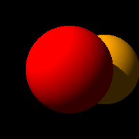
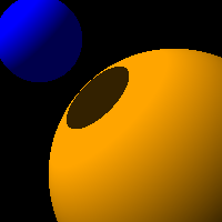
Here are some example test scenes.
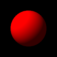
(define test-sphere-1 (make-sphere (make-vec3 0 0 3) 1 (name->rgb 'red))) (define test-camera (make-camera -5 200 200)) (define test-scene-1 (make-scene 'black (list test-sphere-1) (make-light (v3-normalize (make-vec3 -1 1 -1)) (name->rgb 'white)) (make-rgb 0.2 0.2 0.2))) (define test-sphere-2 (make-sphere (make-vec3 1 0 5) 1 (name->rgb 'orange))) (define test-scene-2 (make-scene 'black (list test-sphere-1 test-sphere-2) (make-light (v3-normalize (make-vec3 -1 1 -1)) (name->rgb 'white)) (make-rgb 0.2 0.2 0.2))) (define test-sphere-3 (make-sphere (make-vec3 1 -1 4) 2 (name->rgb 'orange))) (define test-sphere-4 (make-sphere (make-vec3 -1 1 2.75) 0.6 (name->rgb 'blue))) (define test-scene-3 (make-scene 'black (list test-sphere-3 test-sphere-4) (make-light (v3-normalize (make-vec3 -1 1 -0.5)) (name->rgb 'white)) (make-rgb 0.2 0.2 0.3)))
Here are the resulting images for the scenes:
Last revised: November 4, 2010.